Electronics Enclosure
Injection Molding. Snapfits. Master Modeling.

Overview
Key Challenges
U-shape Snap Design
Design for Injection Molding
1 Week Time Constraint
Skills Applied
Master Modeling (SolidWorks)
Injection Molding
Snapfit Design
Electronics Packaging
3D Printing
My Role
Mechanical Engineer - Team of 1
Synapse Product Development
San Francisco, CA
Year
June 2020
About
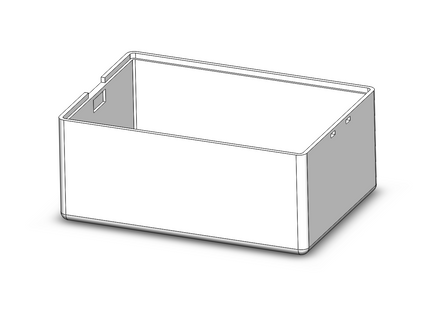
The purpose of this exercise was to learn the process of designing packaging for electronics. This enclosure was designed using a master modeling approach, incorporates a snapfit design, and can be injection molded. It houses a raspberry pi, LiPo battery and connectors.
System Overview


Requirements
1. Must house a PCB, battery, USB connector
2. Must be possible to injection mold the box and lid
3. Must incorporate a snapfit joint connecting lid to box
4. Must design components using a master modeling approach on SolidWorks
Component Selection
Option 1: RPi 4, Power Bank, USB C, Micro USB connectors

Side View
Front View

Option 2: RPi 4, LiPo battery, LiPo Shim, USB connector

Side View
Front View

Option 3: RPi 4, Li-ion battery, Battery hat, USB connectors

Side View
Front View

Decision: Lipo Battery is the most appropriate power source for this application. It will also be accessible if it needs to be replaced.

Snapfit Design
Selecting Type of Snap

Separable vs Inseparable

Decision: Designing a U-shape snap will teach me the fundamentals of snapfit design with an interesting challenge. It is appropriate for this application and will be easy for a user to assemble and disassemble.

Lid to Box Interface
Cross Section
Top View

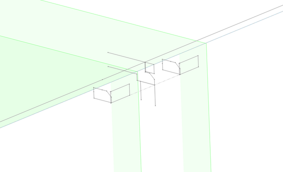
U-Shape snap and tabs or cantilever snap


U-Shape snap on both sides of lid

Decision: Including two small tabs on the lid and two slots in the side of the box wall will make it easy for a user to locate the lid and secure it in place. It will also give me practice designing two different interfaces (snap and tabs).

Benchmark Design
I used the battery door of a TV Remote to get an idea of thicknesses, size ratios, and gaps. I used the dimensions as a reference for a CAD model and made iterations as needed.

Gaps, Thicknesses, Tolerances

Version 1 Dimensions
-
Box Wall Thickness: 2.0mm - 2.5mm
-
Snap Thickness: 1.5mm
3D Printing Tolerance Reference
-
0mm - Press fit
-
0.1mm - Line to line
-
0.2mm - Will slide freely
-
0.3mm - Will rattle
I planned to 3D print 3 lids with varying snap engagements and gaps to test out the difference. This exercise would help me understand how slight changes in dimensions can make an impact on a 3D printed part.
Injection Molding
Concept Sketching

Top View
Bosses
-
PCB can be screwed to box using screw bosses
-
M2.5 Screws
-
Either use threaded inserts or tap holes
Ribs
-
Ribs can be connected to side wall to support bosses
-
Can be used to prevent battery from shifting
-
May use adhesive for battery as well


Tooling and Parting Lines
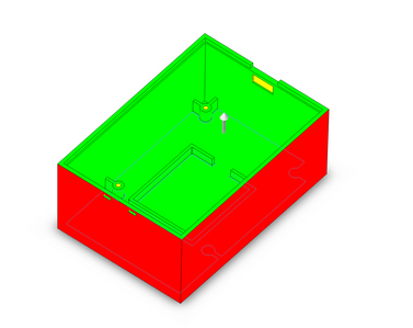
To make the parts possible to injection mold, I had to think about what the tooling would look like and where the parting lines would be. I sketched a cross section of the lid and enclosure and drew the core and cavity. I made sure to consider how the undercuts would be formed using lifters or slides.
I ran a draft analysis in SolidWorks using parting lines as a reference. This helped me see which walls needed drafting. The green indicates that the draft was added.
Master Modeling
Approach

Master modeling was not an essential method for designing this enclosure. I used it solely for the purpose of learning. The diagram above shows an approach that two people could take if they were working on different components (electronics and lid).
Top Master
Sub Master: Electronics
Sub Master: Lid
Box Part
Lid Part
3D Printing
Three lids with varying snap engagement dimensions and one box were 3D printed on a Projet printer using an ABS-like material.
I compared the dimensions from my CAD Model and the physical part 3D printed part. These dimensions will help me make changes to the CAD model for future prints. I will use it as a reference for gaps and tolerances.


Modifying the Design
Modification #1

Problem: Lid is difficult to close
-
Lid is line to line with box edge and must be forced down to close.
Solution: Sand edges of lid until lid slides freely
-
Sand off 0.1mm at a time, then test.
-
When lid stops interfering with box edge, stop sanding and measure.

Results:
-
Lid is no longer interfering with box edge.
-
Removed 0.5mm off every side of the lid.
Modification #2

Problem: Snap is not Engaging
-
Once lid is closed, snap needs to be pushed down and forward to fully engage.
Solution 1: Add a lead-in to box edge
-
Sand the edge of the box where snap interfaces
Solution 2: Increase gap in location of engagement
-
The material may have printed too thick, so snap is not able to fall into gap.
-
Sand the top face of the gap.


Results:
-
Added a 45 degree chamfer.
-
Sanded top face of gap.
-
Problem has minimized but still exists.
Modification #3

Problem: Snap is not Engaging
-
One of the three lids does not engage with the box because too much material was sanded off the edges of the lid.
-
When the lid is being assembled, the side with the tabs bottoms out, creating a gap on the side with the snap.
Solution: Increase snap engagement or do not remove material from back side of lid


Results:
-
The other two lids that were not sanded as drastically are still engaging.
Modification #4


Low Spring Force
High Spring Force
Problem: Snap is not Engaging
-
Once lid is closed, the snap needs to be pushed forward to fully engage with the box.
Solution: Increase spring force of snap
-
Increase thickness or decrease length of snap in future iterations.
-
The snap will require more force to bend back.
-
The snap will not deform as easily.
A simple calculation can be done to find the dimensions that need to be increased in order to increase the load.


Results:
-
The table shows the dimensions that need to be changed.
-
To simulate the effects, I bent one of the snaps forward until it was deformed. It now requires more force to pull back. The spring force helps the snap retract back into place.
Modification #5

Problem:
-
During the steam bath, the lids and the box walls warped.
Solutions:
-
Add gussets to the box side walls.
-
Add ribs to the lids for added support.
Results:
-
Will add features to CAD and print another prototype to test out.
Next Steps

The first version of the enclosure worked reasonably well and only needs a few modifications. The next steps will be to update the CAD files and print a new box and lid.
I will be able to see if my changes helped and if any more changes need to be made.
By doing this exercise, I learned how to make and use a master model, how to design for injection molding, and how to design a snapfit joint.


